Date: Wed Mar 05 2008 - 09:27:09 PST
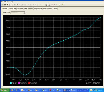
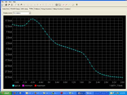
Muniswara,

You don't always need the series [Model] for a differential
buffer.  If there is no current flow between the pads, then
it is OK not to have them.

http://www.vhdl.org/pub/ibis/summits/feb04a/muranyi1.pdf

On the other hand, if you don't include it when you need it,
you may get miscorrelation, as shown on pg. 5 in the following
presentation:
http://www.eda.org/pub/ibis/summits/oct02/muranyi.pdf

As far as I know, you can only detect the presence of pad-to-pad
currents if you sweep the transistor level model's I-V curves in
the double sweep mode as described in the cookbook.  Once you
reduced these I-V curves to just normal single ended models
you won't be able to tell whether there was anything between
the pins.

I hope this helps.

Arpad
-----------------------------------------------------------------


________________________________

From: Muniswara Reddy Vorugu [mailto:Muniswarareddy.Vorugu@arm.com]
Sent: Sunday, March 02, 2008 5:24 AM
To: ibis-users@eda.org; ibis-info@eda.org; ibis@eda-stds.org;
michael.miramak@intel.com; Muranyi, Arpad
Cc: Nidhir Kumar
Subject: please validate the I-V table of the LVDS Buffer


Hi,

I am validating a differential driver, LVDS buffer.

Sections 4.6.1 and 4.6.2 of the COOKBOOK-V4 are insisting on separating
Differential current (Idiff) and Common mode current (Icom).

Then differential current need to modeled as a series [model] :

In my model, I did not find any series [model] key word.


Please clear the following queries:

1: What will happen if differential current and common mode currents are
not separated?

2: Is it possible to identify (seeing the I-V pull-up/pull-down Curve)
that there exists of a resistor (series element) between the pads (pad+
and pad-) and not been modeled. I am attaching the I-V Curves.


This Pull-up and Pull-down tables are generation with this algorithm:

 A1: The sum of potential at the output pads is equal to 2.4. (2 * 1.2)

                      (Vpad+)  + (Vpad-)  = 2*Vref (here 1.2V)   = (
Vref + DeltaV) + ( Vref -  DeltaV)

                      I(IVtable) =I(raw) - Iclamp


A2:  The clamp currents are measured with both the pads being at same
potential.

                      V(pad+) = V(pad-)


Pull-down curve


Pull-up curve related to VCC.


Muniswara Reddy . V

Design engineer, PIPD-IO group,

Bangalore.


--

IMPORTANT NOTICE: The contents of this email and any attachments are
confidential and may also be privileged. If you are not the intended
recipient, please notify the sender immediately and do not disclose the
contents to any other person, use it for any purpose, or store or copy
the information in any medium.  Thank you.


--
This message has been scanned for viruses and
dangerous content by MailScanner, and is
believed to be clean.


--------------------------------------------------------------------
|For help or to subscribe/unsubscribe, e-mail majordomo@eda-stds.org
|with the appropriate command message(s) in the body:
|
|  help
|  subscribe   ibis       <optional e-mail address, if different>
|  subscribe   ibis-users <optional e-mail address, if different>
|  unsubscribe ibis       <optional e-mail address, if different>
|  unsubscribe ibis-users <optional e-mail address, if different>
|
|or e-mail a request to ibis-request@eda-stds.org.
|
|IBIS reflector archives exist under:
|
|  http://www.eda-stds.org/pub/ibis/email_archive/ Recent
|  http://www.eda-stds.org/pub/ibis/users_archive/ Recent
|  http://www.eda-stds.org/pub/ibis/email/         E-mail since 1993