Date: Fri Aug 15 2014 - 16:02:06 PDT
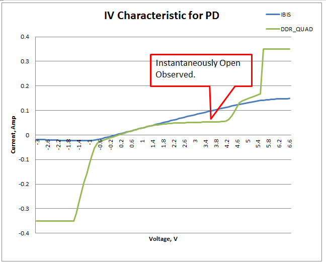
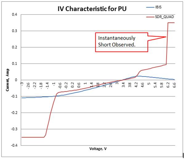
Hi Arpad,

Thanks for you detail explanation. You just cleared my doubts.
However, it seems like the measurement result (DDR_QUAL) is not correlated with IBIS model result(IBIS) after 1.8V.
Can you please advise on how to reduce the variation between the measurement and IBIS model result.
Yes, you are right. 350mA is the current limiter of the equipment.

Best Regards,
Ai Heong
From: owner-ibis-users@eda.org [mailto:owner-ibis-users@eda.org] On Behalf Of Muranyi, Arpad
Sent: Friday, August 15, 2014 3:33 PM
To: ibis-users@eda.org
Subject: [IBIS-Users] RE: IBIS Correlation Issues on IV Part

Ai Heong,

Thanks for explaining what you meant.

What you call "instantaneous open" is basically the
saturation region of the output transistor.  In that
region, it acts as a constant current source.  The
circuit is not "open" (this is where I was confused
by your terminology), it is just acting as a current
source.  Some buffers/busses are designed to operate
in this region.

Transistors also have a linear region, where they look
like a resistor.  Some buffers/busses are designed to
operate in this region.

There is nothing wrong with either approach, it all
depends on what the designers wanted to achieve.

What you call "instantaneous short" is way outside the
normal operating region.  It is not the current of the
parasitic diode.  You can see that around -0.6 and +4.2
or so volts.  The jump at 5.4 or 6 volt is where the
circuit can't operate (normally) as designed and all
kinds of weird things start happening.  This is usually
where things can start making fireworks, etc...  But the
horizontal line blow -1.4 and above 5.5 volt seems to be
from your measurement equipment's current limiter (both
being set to 350 mA)...

In short, there is nothing wrong with what you measured,
you just need to understand what it means.

I hope this helps,

Arpad
============================================================


From: Tan, Ai-Heong [mailto:Ai-Heong.Tan@spansion.com]
Sent: Friday, August 15, 2014 5:18 PM
To: Muranyi, Arpad; ibis-users@eda.org<mailto:ibis-users@eda.org>
Subject: RE: IBIS Correlation Issues on IV Part

Hi Arpad,

Thanks for your quick response.
FYI, operating voltage of this device is -0.7V - 3.6V.
Instantaneous open refer to the current remain constant with voltage applied.
For example, by looking at the PD curve, the measurement result(DDR Qual) shows the current remain constant at 1.8V-3.9V.
Do you think the measurement result(DDR Qual) is valid for the PD part?
Instantaneous short refer to the current shoot up with a slight voltage changes. I am not worry on this as this happened at diode region.
Thanks,
Ai Heong

From: owner-ibis-users@eda.org<mailto:owner-ibis-users@eda.org> [mailto:owner-ibis-users@eda.org] On Behalf Of Muranyi, Arpad
Sent: Friday, August 15, 2014 2:09 PM
To: ibis-users@eda.org<mailto:ibis-users@eda.org>
Subject: [IBIS-Users] RE: IBIS Correlation Issues on IV Part

Ai Heong,

Could you please explain what you mean by "instantaneous open/short"?
I don't quite understand your terminology...

Thanks,

Arpad
=====================================================================

From: owner-ibis-users@eda.org<mailto:owner-ibis-users@eda.org> [mailto:owner-ibis-users@eda.org] On Behalf Of Tan, Ai-Heong
Sent: Friday, August 15, 2014 3:58 PM
To: ibis-users@eda.org<mailto:ibis-users@eda.org>
Subject: [IBIS-Users] IBIS Correlation Issues on IV Part

Hi EXPERTS,

Currently, I am performing IV curve measurement for a flash package (SOIC16 package).
I am using Source Measurement Unit (SMU Keithley 4200), DC Power Supply (Keithley 2230-30-1), Arbitrary  Waveform Generator (AWG Tektronix 5200C), and a 4 layer PCB breakout board for the setup.
The flash package was placed in a socket which soldered on top of the PCB breakout board. Then, the AWG is used to perform the programming/triggering on the flash device in order to generate a HIGH / LOW output waveform.
The SMU is connected to the output of the flash device and I sweep the voltage from -0.7V - 3.6V (operating region of the flash).
Please refer to the figure below for the IV curve measurement on the Pullup and Pulldown which I overlapped it with the IBIS model result.
I observed there were an instantaneous open happened at the region 1.8 - 3.3V for the Pulldown result of each IO.
May I know why this happened and how to solve it.
Besides, can everyone please advise on the quality of the IBIS model and any constructive suggestions/comments for improvement are appreciated sincerely.
Thanks and I hope to hearing from you soon.

[cid:image001.png@01CFB6EA.25EBDA10][cid:image002.jpg@01CFB6EA.AE8CF6B0]


Best Regards,
Ai Heong


--
This message has been scanned for viruses and
dangerous content by MailScanner<http://www.mailscanner.info/>, and is
believed to be clean.

--
This message has been scanned for viruses and
dangerous content by MailScanner<http://www.mailscanner.info/>, and is
believed to be clean.

--
This message has been scanned for viruses and
dangerous content by MailScanner<http://www.mailscanner.info/>, and is
believed to be clean.

--
This message has been scanned for viruses and
dangerous content by MailScanner, and is
believed to be clean.


--------------------------------------------------------------------
|For help or to subscribe/unsubscribe, e-mail mikelabonte@eda-stds.org
|or ibis-request@eda-stds.org
|
|IBIS reflector archives exist under:
|
|  http://www.eda-stds.org/ibis/email_archive/ Recent
|  http://www.eda-stds.org/ibis/users_archive/ Recent
|  http://www.eda-stds.org/ibis/email/         E-mail since 1993