Date: Thu Sep 19 2013 - 07:47:14 PDT
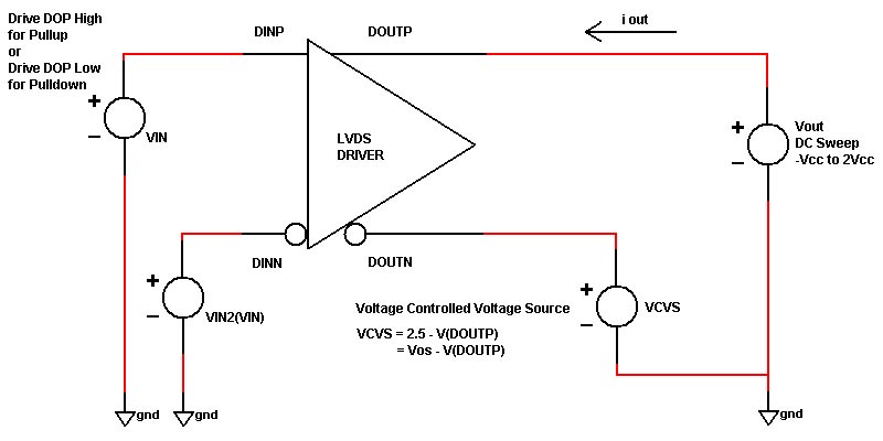
Running such simulations in the DC sweep mode may be
the problem.  If the model has flip/flops in it, there
is a possibility that as the DC sweep progresses with
different values, the flip/flops initialize themselves
to different states.  As a result part of your curve
might represent one state and other parts of your curve
might represent a different state.  This could explain
why your I-V curve is so strange.  I would recommend
to do this using a time domain simulation and a ramp
source.  But make sure that the ramp goes slowly, in
the milli-second range.

Arpad
==========================================================

From: Andrey Babintsev [mailto:b13285@freescale.com]
Sent: Thursday, September 19, 2013 9:12 AM
To: Muranyi, Arpad
Cc: ibis-users@eda.org
Subject: Re: [IBIS-Users] {Spam?} {Filename?} LVDS IBIS model - simulation issue

Arpad,
In this case DC sweep is a series of independent DC solutions.

Tom,
You are right, Vcm is changing unexpectedly, I will investigate further why it is changing and how to control it.
Can you share how you generate LVDS models, how you control the inverted pin?
Is it appropriate way:
[http://www.eetimes.com/document.asp?doc_id=1225499]
(c) http://www.eetimes.com/document.asp?doc_id=1225499

Regards,
Andrey


On 09/19/2013 02:11 AM, Muranyi, Arpad wrote:

Just another question about generating the I-V data:


How fast are you sweeping the voltage when you measure the

current?  Is it in the ns, us, ms range?  The reason I am

asking is because if you sweep it too fast, you might actually

be measuring parasitic capacitance on the die (I=C*dV/dt)...


Thanks,


Arpad

===============================================================


-----Original Message-----

From: Tom Dagostino [mailto:tom@teraspeed.com]

Sent: Wednesday, September 18, 2013 4:19 PM

To: 'Babintsev Andrey-B13285'; Muranyi, Arpad; ibis-users@eda.org<mailto:ibis-users@eda.org>

Subject: RE: [IBIS-Users] {Spam?} {Filename?} LVDS IBIS model - simulation issue


Andrey


I've tried this kind of extraction also. The curves looked much more CMOS

current source like than you are showing for the pulldown.  It still looks

like your feedback loop is in control of the driver and it is not happy with

Vcm.


Tom Dagostino


Teraspeed Labs

9999 SW Wilshire St.

Suite 102

Portland, OR 97225

USA


971-279-5325  Office

971-279-5326   FAX

503-430-1065  Cell


tom@teraspeed.com<mailto:tom@teraspeed.com>

www.teraspeed.com<http://www.teraspeed.com>


Teraspeed Consulting Group LLC

16 Stormy Brook Road

Falmouth, ME 04105

401-284-1827


-----Original Message-----

From: Babintsev Andrey-B13285 [mailto:B13285@freescale.com]

Sent: Wednesday, September 18, 2013 12:57 PM

To: tom@teraspeed.com<mailto:tom@teraspeed.com>; 'Muranyi, Arpad'; ibis-users@eda.org<mailto:ibis-users@eda.org>

Subject: RE: [IBIS-Users] {Spam?} {Filename?} LVDS IBIS model - simulation

issue


Arpad, Tom,


Thank you for your responses.

I used 50 Ohm because it is MLB interface. I called it LVDS to make it clear

that I was speaking about low swing differential signal.

I inverted the curve polarity on the plot and made both of them ground

relative to make it convenient to compare source and sink currents. In the

IBIS models they were put with correct polarity, pullUp - Vdd relative, in

accordance with IBIS standard and IBIS cookbook.

While DC sweep on the non-inverted output was done for IV curves extraction,

the inverted output was controlled by the voltage dependent voltage source

v=2*Vos-v(padp), Vos ~ 1.25V (depending on conditions).

Actually the issue was observed for slow and typ cases while for fast case

the models are in good agreement with spice models (Vmax, Vmin, Trise,

Tfall, Duty cycle matched  reference waveforms).


Regards,

Andrey

________________________________________

From: owner-ibis-users@eda.org<mailto:owner-ibis-users@eda.org> [owner-ibis-users@eda.org<mailto:owner-ibis-users@eda.org>] on behalf of Tom

Dagostino [tom@teraspeed.com<mailto:tom@teraspeed.com>]

Sent: Wednesday, September 18, 2013 10:39 PM

To: 'Muranyi, Arpad'; ibis-users@eda.org<mailto:ibis-users@eda.org>

Subject: RE: [IBIS-Users] {Spam?} {Filename?} LVDS IBIS model - simulation

issue


Andrey


I've modeled a lot of LVDS buffers in the past and this is definitely the

strangest looking pulldown IV curve I've ever seen.  And as Arpad says it

does not at all look like a reasonable result.


First, why are you loading your LVDS buffer with a 50 Ohm differential

termination?  Most I have seen are looking for 100Ohms.


Have you inverted the pulldown's polarity?  I would also expect to see the

pulldown curve to have positive current between ground and Vdd.


LVDS buffers have a feedback loop in them so stabilize the Vcm of the

buffer.  Usually this only affect the pullup IV curve but sometimes only the

pulldown.  This makes extracting the IV characteristics of the controlled

device difficult.  The feedback is fighting the curve tracer that is

measuring the IV characteristics.  While you are doing the IV sweep you are

by definition changing Vcm and the feedback is trying to correct for this.


BTW, Ip = -In.  One is sourcing current and the other sinking.  The sourcing

should have negative currents and the sinking positive.


Tom Dagostino


Teraspeed Labs

9999 SW Wilshire St.

Suite 102

Portland, OR 97225

USA


971-279-5325  Office

971-279-5326   FAX

503-430-1065  Cell


tom@teraspeed.com<mailto:tom@teraspeed.com><mailto:tom@teraspeed.com><mailto:tom@teraspeed.com>

www.teraspeed.com<http://www.teraspeed.com><http://www.teraspeed.com/><http://www.teraspeed.com/>


Teraspeed Consulting Group LLC

16 Stormy Brook Road

Falmouth, ME 04105

401-284-1827


From: owner-ibis-users@eda.org<mailto:owner-ibis-users@eda.org> [mailto:owner-ibis-users@eda.org] On Behalf

Of Muranyi, Arpad

Sent: Wednesday, September 18, 2013 8:31 AM

To: ibis-users@eda.org<mailto:ibis-users@eda.org>

Subject: RE: [IBIS-Users] {Spam?} {Filename?} LVDS IBIS model - simulation

issue


Andrey,


I am not sure that your PD I-V curve is correct.


First of all, it should have a positive sign, but its shape doesn't look

right either.


Can you describe how you generated these I-V curves?


Thanks,


Arpad

========================================================


From: owner-ibis-users@eda.org<mailto:owner-ibis-users@eda.org><mailto:owner-ibis-users@eda.org><mailto:owner-ibis-users@eda.org>

[mailto:owner-ibis-users@eda.org] On Behalf Of Andrey Babintsev

Sent: Wednesday, September 18, 2013 9:38 AM

To: ibis-users@eda.org<mailto:ibis-users@eda.org><mailto:ibis-users@eda.org><mailto:ibis-users@eda.org>

Subject: Re: [IBIS-Users] {Spam?} {Filename?} LVDS IBIS model - simulation

issue


Re-sending with updated attachment


Hi,


I am making IBIS models for LVDS (low voltage differential signal) IO

buffer.

To model an LVDS buffer I created the following test circuit, assigned the

generated IBIS model to both buffers, set one buffer as inverted output.

[cid:image001.png@01CEB462.5402D6F0]


Problem:

In the image below the YELLOW waveform is what I saw and the PURPLE waveform

is what I expected to see.

[cid:image002.png@01CEB462.5402D6F0]

YELLOW = IBIS model

PURPLE = Spice ( reference ) model


Here is combined pullUp (yellow) and pullDown (green) IV curves (actually it

is spice curves from which IV tables were derived):

[cid:image003.png@01CEB462.5402D6F0]


Lets assume that simulator tries to find operational point for LVDS buffer

driving high. Then for the non-inverted buffer a point (Vp, Ip) will be

taken from pullUp table, for the inverted buffer a point (Vn, In) from

pullDown table, the following conditions should be satisfied: Ip = In, Vp -

Vn = Ip*50. On the image above it is seen that there are 2 points satisfying

the condition: Vp =~  1.45V and Vp =~ 2.2V. Seems that something like that

happened during simulation and simulator got to the second point. (BTW,

there are 60 points for the region 0.9 - 1.6V and 10 points for the region

1.6-2.5V in the IBIS model IV tables).


Question:

What can be done to resolve this situation? Should IV tables or another IBIS

structures be modified and how? I am making ibis ver. 4.2 models.


Thanks,

Andrey


On 09/18/2013 06:33 PM, Andrey Babintsev wrote:


Warning: This message has had one or more attachments removed

(fail.min.png). Please read the "EDA-Attachment-Warning.txt" attachment(s)

for more information.

Hi,


I am making IBIS models for LVDS (low voltage differential signal) IO

buffer.

To model an LVDS buffer I created the following test circuit, assigned the

generated IBIS model to both buffers, set one buffer as inverted output.

[cid:part1.07090501.06090707@freescale.com]


Problem:

In the image below the YELLOW waveform is what I saw and the PURPLE waveform

is what I expected to see.

[cid:part2.00080404.04020708@freescale.com]

YELLOW = IBIS model

PURPLE = Spice ( reference ) model


Here is combined pullUp (yellow) and pullDown (green) IV curves (actually it

is spice curves from which IV tables were derived):

[cid:part3.05090108.02030307@freescale.com]


Lets assume that simulator tries to find operational point for LVDS buffer

driving high. Then for the non-inverted buffer a point (Vp, Ip) will be

taken from pullUp table, for the inverted buffer a point (Vn, In) from

pullDown table, the following conditions should be satisfied: Ip = In, Vp -

Vn = Ip*50. On the image above it is seen that there are 2 points satisfying

the condition: Vp =~  1.45V and Vp =~ 2.2V. Seems that something like that

happened during simulation and simulator got to the second point. (BTW,

there are 60 points for the region 0.9 - 1.6V and 10 points for the region

1.6-2.5V in the IBIS model IV tables).


Question:

What can be done to resolve this situation? Should IV tables or another IBIS

structures be modified and how? I am making ibis ver. 4.2 models.


Thanks,

Andrey


--

This message has been scanned for viruses and dangerous content by

MailScanner<http://www.mailscanner.info/><http://www.mailscanner.info/>, and is believed to be clean.


--

This message has been scanned for viruses and dangerous content by

MailScanner<http://www.mailscanner.info/><http://www.mailscanner.info/>, and is believed to be clean.


--

This message has been scanned for viruses and dangerous content by

MailScanner<http://www.mailscanner.info/><http://www.mailscanner.info/>, and is believed to be clean.


--
This message has been scanned for viruses and
dangerous content by MailScanner, and is
believed to be clean.


--------------------------------------------------------------------
|For help or to subscribe/unsubscribe, e-mail mikelabonte@eda-stds.org
|or ibis-request@eda-stds.org
|
|IBIS reflector archives exist under:
|
|  http://www.eda-stds.org/ibis/email_archive/ Recent
|  http://www.eda-stds.org/ibis/users_archive/ Recent
|  http://www.eda-stds.org/ibis/email/         E-mail since 1993